V Auxiliary Power Schematic Wiring Diagram. A wiring diagram is a simple visual representation of the physical connections and physical layout of an electrical system or circuit. Almost all electrical wiring circuits are the following items: Power supply.
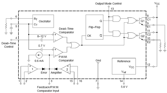
DC to DC Converter circuit TL494 12V to 30V Adjustable ... (Virginia Morgan) It shows the components of the circuit as simplified shapes, and the power and signal connections between the devices. A wiring diagram is a simplified conventional pictorial representation of an electrical circuit. Free electronics schematic diagrams downloads, electronics CAD software, electronics circuit and wiring diagrams, guitar wiring diagrams, tube amplifier schematics, electronics repair manuals, amplifier layout diagrams,PCB software for making printed circuit boards, amplifier design software.
Most of the diagrams in this book are shown in two Wiring diagrams or connection diagrams include all of the devices in the system and show their All control devices are shown between vertical lines which represent the source of control power, and.
Legend of wiring diagram air suspension.
Power Supply Components - Circuit Diagram Images
Variable power supply circuit, 0-50v at 3A with PCB ...
ArduPicLab: An isolated analog output for Arduino Uno
250 to 5000 watts PWM DC/AC 220V Power Inverter - Gallery ...
Variable / Adjustable DC Power Supply 1.2V - 25V using ...
DC to DC Converter circuit TL494 12V to 30V Adjustable ...
Schematic Power Amp 2000w
33 480 Volt To 120 Volt Transformer Wiring Diagram - Wire ...
Inverter Circuit: 100W Power Inverter Circuit
This form of electrical diagram is sometimes referred to as a "schematic" or "line" diagram. Wiring diagrams are made up of two things: symbols that represent the components in the circuit, and lines that represent the connections between them. "WIRING DIAGRAMS" vs "LINE DIAGRAMS". CAR wiring diagram software Provide the whole view of the wiring diagram in a car,component location diagram and maintenance method.
Related Posts :
Vac Generator Wiring Diagram Vac Generator Wiring Diagram. This pictorial diagram shows us the. Built for use in power supplies of. Lucey Blue: Marine toli…Read More...
Vac Ac Motor Wiring Diagram Vac Ac Motor Wiring Diagram. Specifically, rotational energy is produced by utilizing the force of magnetic fields induced by alternating c…Read More...
Vac 3 Phase Motor Wiring Diagram Vac 3 Phase Motor Wiring Diagram. Three-phase asynchronous motors can be connected to a single-phase network using phase-shifting elements.…Read More...
V Wiring Diagrams Lighting V Wiring Diagrams Lighting. For example, the proper location of light fixtures and electrical outlets can. A wiring diagram is a visual rep…Read More...
Vac Led Lights 3 Wire Diagram Vac Led Lights 3 Wire Diagram. Ordinary LED flashers turn the LED on and off abruptly, which can get a little irritating after a while. In …Read More...
0 Response to "V Auxiliary Power Schematic Wiring Diagram"
Post a Comment