77 Crank Sensor Wiring Diagram
77 Crank Sensor Wiring Diagram. For example, if if the sensor wires are not secured properly. In some cars, the intermittent stalling can also be caused by a problem with the crankshaft position sensor wiring.

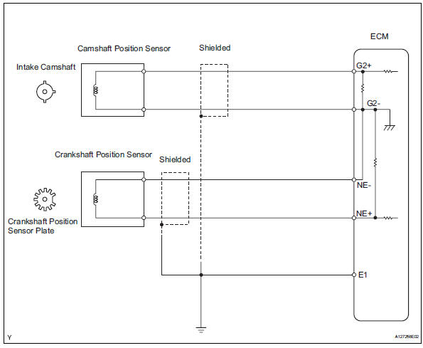
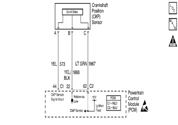
The wiring diagram says the orange with blue wire goes into the cavity on the left if you look at the face of the connector (non wire side) with the key facing up.
I was told the crank & cam sensor wires need to be wired differently any input?
Wiring Diagram For Crank Position Sensor On 95 Chevy S10 W ...

Crank Sensor Wiring Diagram - Wiring Diagram and Schematic
98 Chevy Z71 K1500 Sensor Wiring Diagram - Wiring Diagram ...
Crank Sensor Wiring Diagram - Style Guru: Fashion, Glitz ...

Bmw M57 Wiring Diagram - Wiring Diagram Schema

Crank Sensor Wiring Diagram - Wiring Diagram and Schematic
Wiring Diagram For Crank Position Sensor On 95 Chev S10 W ...

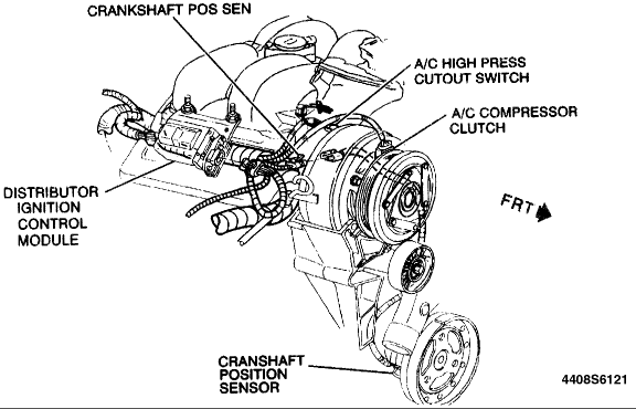
Repair Guides
Crank Sensor Diagram - Wiring Diagram Dash
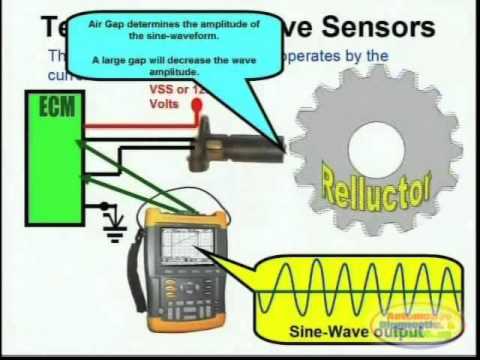
Crank Sensor Hall Effect Cam Sensor Magnetic Cam Sensor Hall Effect Sensor GND Manifold/Baro Pressure. A crank sensor is an electronic device used in an internal combustion engine, both petrol and diesel, to monitor the position or rotational speed of the crankshaft. These. crank sensor connector. enable contact between cables, electronic components, wires, etc.

0 Response to "77 Crank Sensor Wiring Diagram"
Post a Comment