V V Transformer Wiring Diagram Schematic
V V Transformer Wiring Diagram Schematic. WIRING DIAGRAM A wiring diagram shows, as closely as possible, the actual location of all component parts of the device. The choice of the wiring diagram of the substation, and therefore of the related equipment, depends on several factors such as: - the number of power lines - the number of transformers - the requirements of the service.
A wiring diagram is a streamlined traditional photographic depiction of an electric.
A proper wiring diagram will be labeled and show connections in a way that prevents confusion about how connections are made.
480 Volt to 120 Volt Transformer Wiring Diagram Sample ...
480 Volt to 120 Volt Transformer Wiring Diagram Sample ...
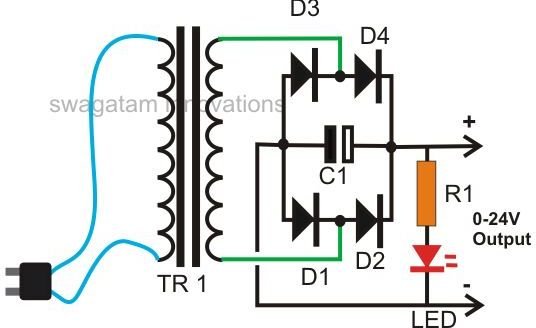
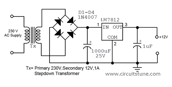
How to Build a Homemade 24 Volt AC to DC 20 Amp ...
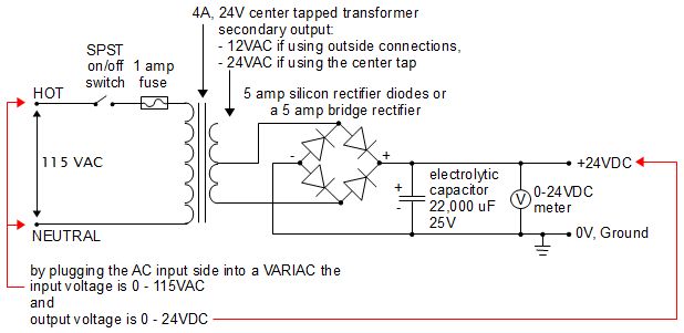
24V DC Power Supply (homemade/DIY)
480V To 120V Transformer Wiring Diagram | Fuse Box And ...

Aprilaire 600a 24v wiring help - DoItYourself.com ...

Transformer Connection Diagrams - Alexander Publications

JMK Electronics Best training Provide for Electronics ...
Power distribution configurations with three 3ph power lines
The choice of the wiring diagram of the substation, and therefore of the related equipment, depends on several factors such as: - the number of power lines - the number of transformers - the requirements of the service. Type of wiring diagram Wiring Diagram VS Schematic Diagram How to read a wiring diagram: Symbols you should know Wiring A wiring diagram is a visual representation of components and wires related to an electrical connection. Circuit layouts and schematic diagrams are a simple and effective way of showing pictorially the electrical connections, components and operation of Basic electrical and electronic graphical symbols called Schematic Symbols are commonly used within circuit diagrams, schematics and computer.

0 Response to "V V Transformer Wiring Diagram Schematic"
Post a Comment