V 3 Phase Wind Generator Wiring Diagram
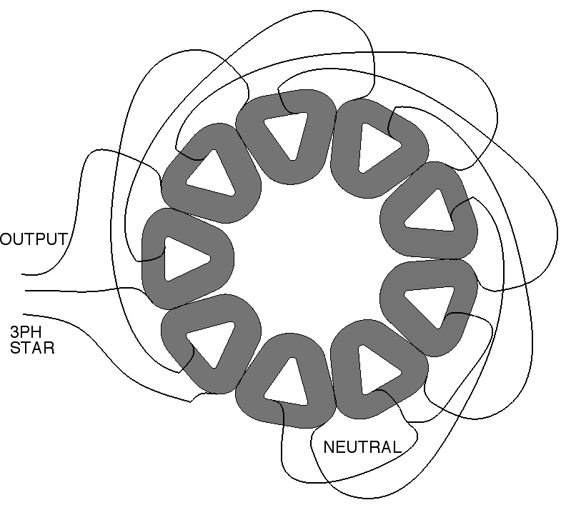
V 3 Phase Wind Generator Wiring Diagram. In the event the motor is the sole electrical device which is to be powered then we can concentrate on the price of replacing the motor with one of exactly the same specifications, but by means of the available power at the place. The difference between them is that in The STAR wiring Circuits you get more voltage with less rotation ( Depending on Wind Speed or Stream Water Current Flow or other media Coil and the ending wire of the third Coil goes to the Connectors.

Type of wiring diagram Wiring Diagram VS Schematic Diagram How to read a wiring diagram: Symbols you should know Wiring Diagram Examples How to draw a wiring diagram with Edraw?
Rotating magnetic field - is the basic concept of electric motors and generators.

Wiring Diagram PDF: 12v 3 Phase Wind Generator Wiring Diagram
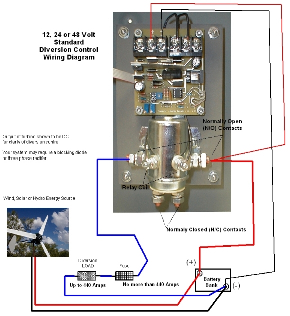
HVM charge controller 440 amp 10,00 watt 12 / 24 or 48 ...
WIRING | Hugh Piggott's blog

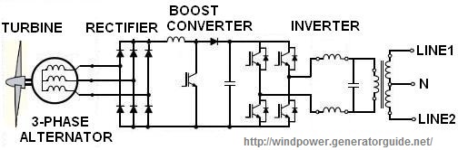
News Info: How to build a 3 phase wind generator

New Wiring Diagram Three Phase Generator #diagram # ...

Wind Turbine Generator 3 Phase Wiring Diagram - All of ...

12 Volt Hybrid Charge Controller DIG with 3 Phase Wind ...

Wind Turbine Generator 3 Phase Wiring Diagram - Complete ...
Let it Build plan: Where to get Homemade wind turbine ...
SLD - Phoenix with wind gen - off-grid. Three-phase induction motors with a wound rotor were usually used in devices with severe starting conditions, for example, as crane AC motors, or to. An alternator has three-phase winding with terminals A-A', B-B' and C- C' Phasor diagrams showing the phase and line voltage relationships for the two phase sequences ABC and ACB are shown in Figs.

0 Response to "V 3 Phase Wind Generator Wiring Diagram"
Post a Comment