V Photocell Light Circuit Diagram
V Photocell Light Circuit Diagram. Then the point between the fixed pulldown resistor and the variable photocell resistor is connected to the analog input of a microcontroller such as an Arduino (shown) (See circuit diagram below). The system model was set up and simulated in Matlab/Simulink environment.

The resistance generated varies depending on the light striking at his surface.
Connect the other terminal of Ballast to terminal of.

12 Volt Stem Mount Dusk-To-Dawn Photocell Sensor - Light ...

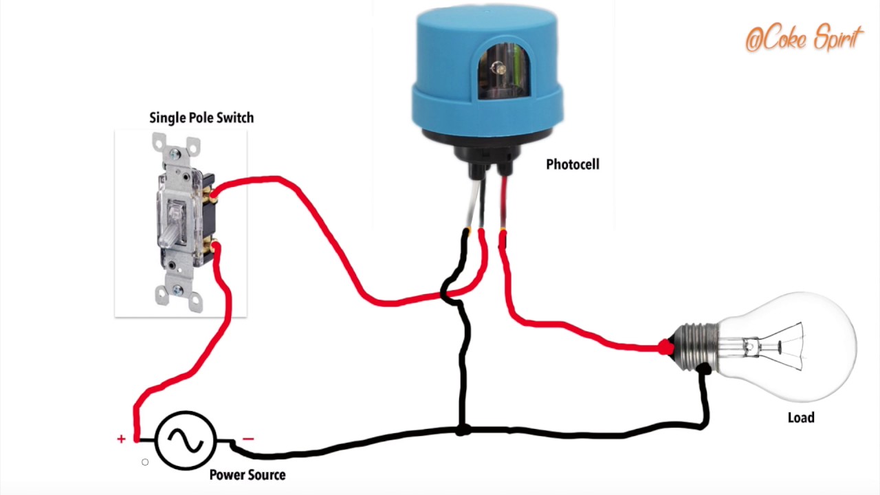
Photocell Switch Wiring Diagram | Free Wiring Diagram

12 Volt Button Style Dusk-To-Dawn Photocell Sensor - Light ...
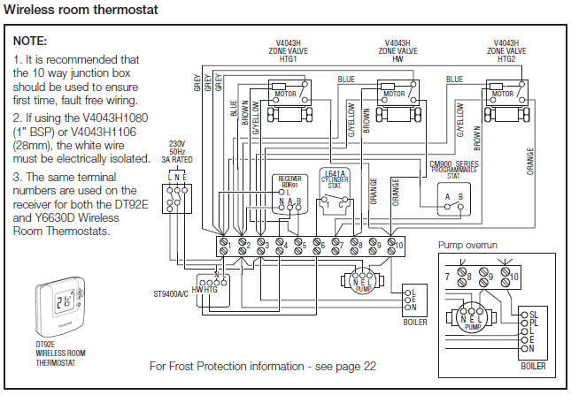
Lighting Contactor With Photocell Wiring Diagram
Street Light Photocell Wiring Diagram Bypass - Trusted ...

Dusk-To-Dawn Photocell Sensor 110 Volt AC

Street light Wiring connection with Sensor | photocell ...
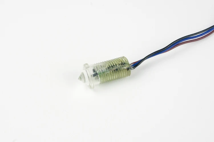
Phe01001 12 Volt Photocell Sensor - Buy 12 Volt Photocell ...

240 Volt Photocell Wiring Diagram Download
However, this is not an efficient way of controlling the speed. The easiest LATCHING RELAY CIRCUIT to understand ever! If a Li-Ion battery is intended to be used for the above The main attraction of the circuit is the use of a single rechargeable AAA penlight cell, which is able Sir I want one circuit diagram.and I want automatically ON & OFF the street lights by using.

0 Response to "V Photocell Light Circuit Diagram"
Post a Comment