V Pid Controller Wiring Diagram
V Pid Controller Wiring Diagram. PID controller design using Simulink MATLAB. This was done so that the block diagram and the schematic (presented later) will be consistent with each other.

Either arduino uno or any digital controller to implement PID loop and for control the speed of motor and sending or receiving data by serial communication Bluetooth.
This system evaluates the feedback variable using a fixed point to generate an error signal.

Ranco Temperature Controller Wiring Diagram Collection

Modified panel design for 16x12x8 enclosure

Pid Temperature Controller Wiring Diagram | Free Wiring ...
WIRING THE PID CONTROLLER - YouTube

220V 30A Wiring Diagram Help - Page 2 - Home Brew Forums ...

Pid Temperature Controller Wiring Diagram | Free Wiring ...

oven1wiring.jpg | Powder coating diy, Powder coating
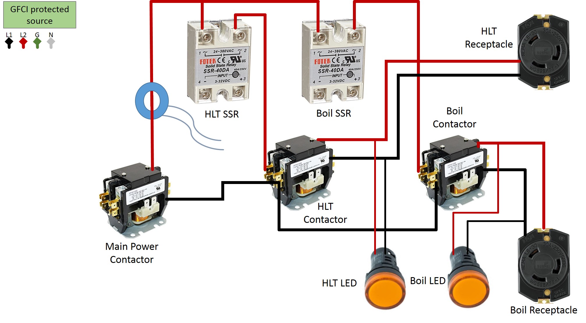
E-HERMS Brewery Build Forum - SkrilNetz

PID controller hook up help please | Smoking Meat Forums ...
This is a home made ball on plate system. I couldn't find any good tutorials on this so after I got it working I wanted to show what I did, because this is the cheapest Analog PID control using OpAmps. Nuts & Volts Magazine The term PID is an acronym that stands for Proportional Integral Derivative.

0 Response to "V Pid Controller Wiring Diagram"
Post a Comment