V Schematic Wiring Diagram
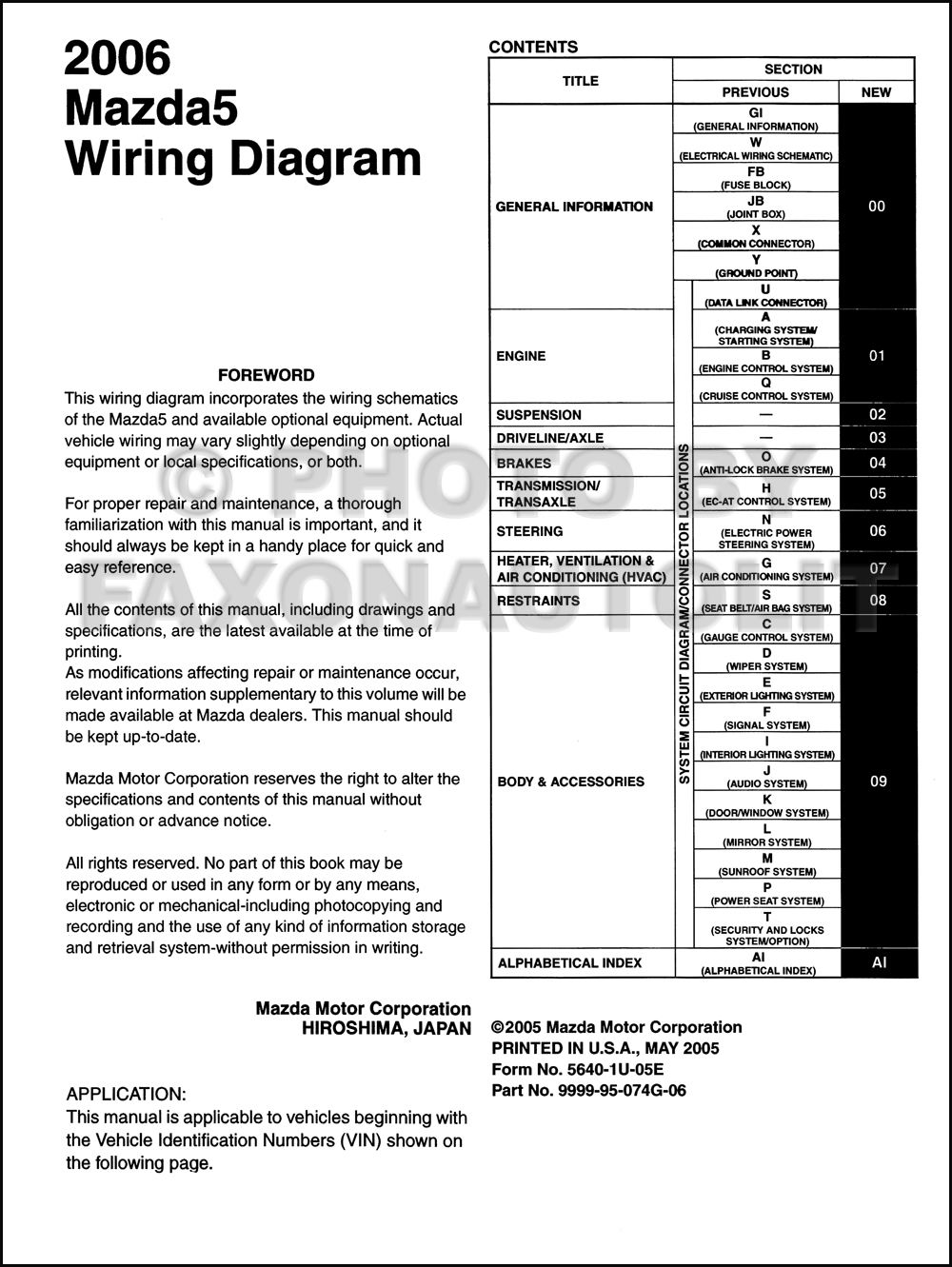
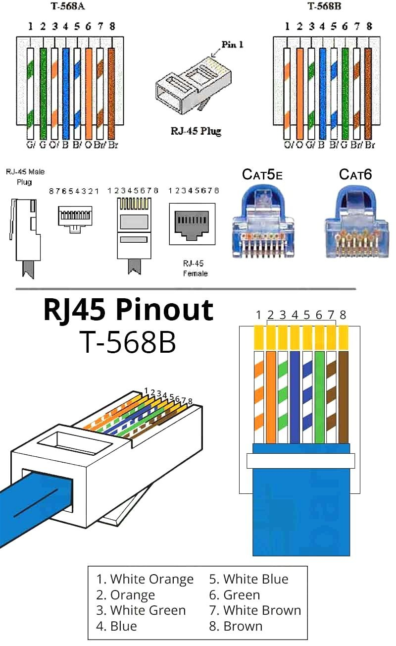
V Schematic Wiring Diagram. A wiring diagram is a simplified conventional pictorial representation of an electrical circuit. According to earlier, the lines in a Schematic Wiring Diagram signifies wires.
A wiring diagram is a visual representation of components and wires related to an electrical connection.
The US Federal Communications Commission (or FCC) regulates interstate and international communications by radio and television, wire and cable, and satellite.
A wiring diagram is a type of schematic that uses abstract pictorial symbols to show all the interconnections of components in a system. Type of wiring diagram Wiring Diagram VS Schematic Diagram How to read a wiring diagram: Symbols you should know Wiring Diagram Examples How to draw a wiring diagram with Edraw? Table of Contents System Block Diagram Power Block Diagram BOM Configuration Revision History Revision History FUNC TEST Power Aliases SIGNAL ALIAS CPU FSB CPU Power & Ground CPU Decoupling eXtended Debug Port(MiniXDP) MCP CPU Interface MCP Memory Interface MCP.


0 Response to "V Schematic Wiring Diagram"
Post a Comment