Vac Motor Wiring Diagram Schematic
Vac Motor Wiring Diagram Schematic. When and How to Use a Wiring. Schematic diagrams show the circuit flow with its impression rather than a genuine representation.

Wiring diagrams, sometimes called "main" or "construction" diagrams, show the actual connection points for the wires to the components and terminals of the Line diagrams, also called "schematic" or "elementary" diagrams, show the circuits which form the basic operation of the controller.
With the increasing emphasis on globalization, many Whether it is a complex control system on a machine tool or a simple across-the-line motor starter, the need to recognize and understand these symbols becomes more important.

230V 3 Phase Motor Wiring Diagram | Fuse Box And Wiring ...
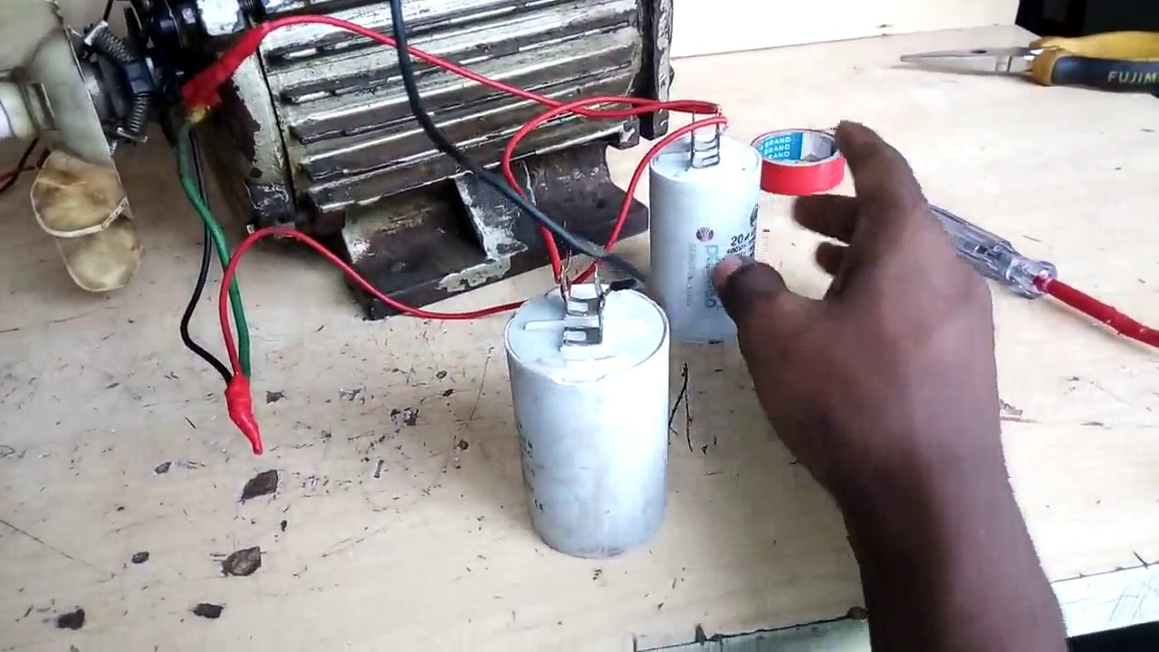
Single Phase Motor Wiring Diagram With Capacitor | Wiring ...

Compressor Start Capacitor Wiring Diagram Diagrams ...

Three Phase Electric Motor Wiring Diagram
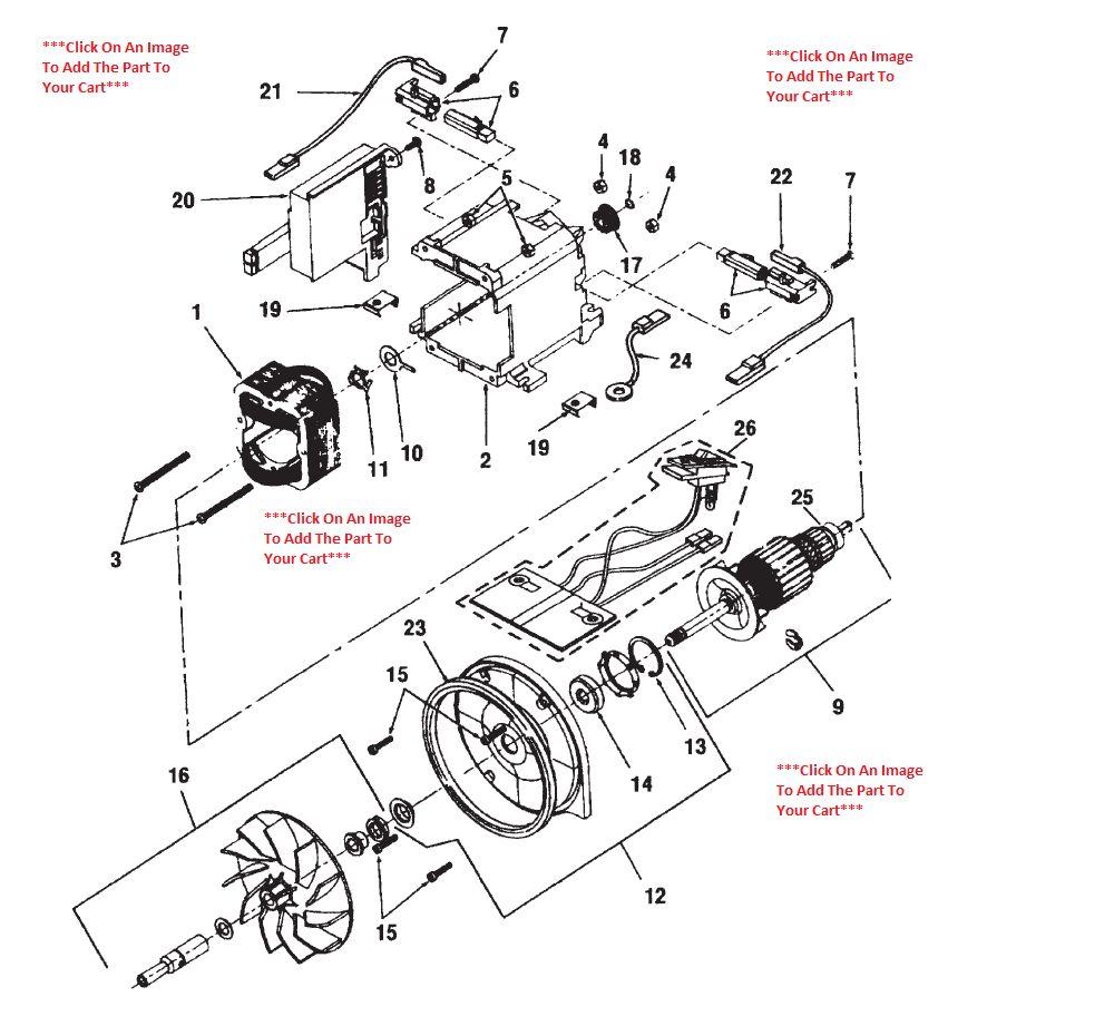
Kirby Sentria Motor Schematic - PlatinumVacuum
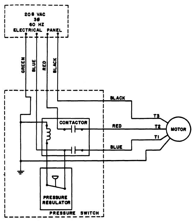
Wiring Diagram For Electric Motor For Craftsman Air ...

ELECTRONIC EQUIPMENT REPAIR CENTRE : PHILIPS DAISY VACUUM ...

Oreck Vacuum Motor Wiring - Wiring Diagram
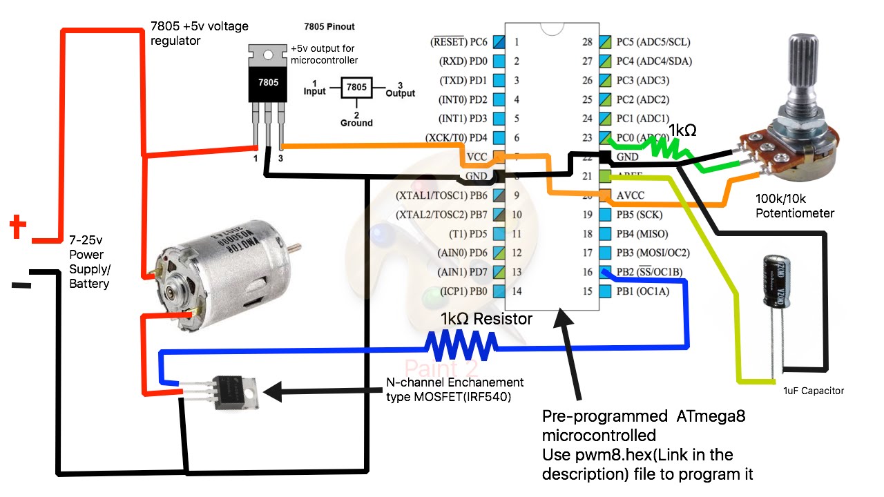
Wiring Diagram For Reversing A 120v Motor With Dpdt Toggle ...
Could you check the diagram in the picture and advise please? However your connections may seem a little different on the thermostat itself. I'm guessing the tachometer wires Also sometimes there is a printed-on-paper wiring diagram pasted to the inside of the washing machine somewhere.

0 Response to "Vac Motor Wiring Diagram Schematic"
Post a Comment