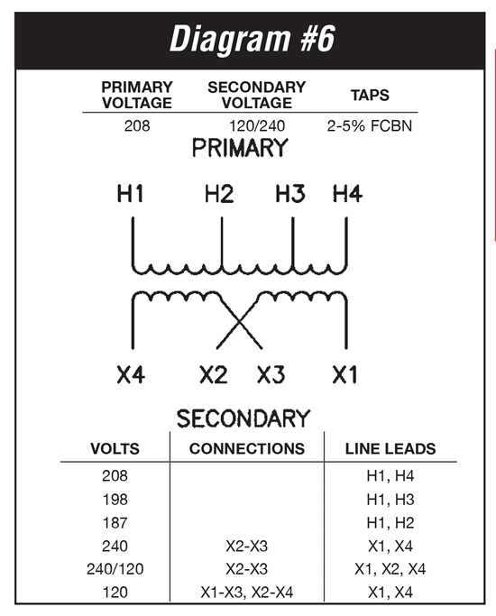
V Watt Transformer Wiring Diagram
V Watt Transformer Wiring Diagram. They are called transformers because they transform voltage and current from one level to Watts is equal to the volts times the amps. There is a little loss of power in a transformer due to the.
In essence, electrical substations consist of power transformers, circuit breakers, and secondary systems for protection, load control and metering.
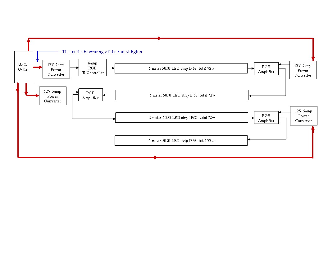
This pictorial diagram shows us the physical links that are.

3-Wire 240V Single-Phase Power Measurements | EEWeb Community

480v Ballast Wiring Diagram - Wiring Diagram Networks
Transformer 240 To 120 | Tyres2c
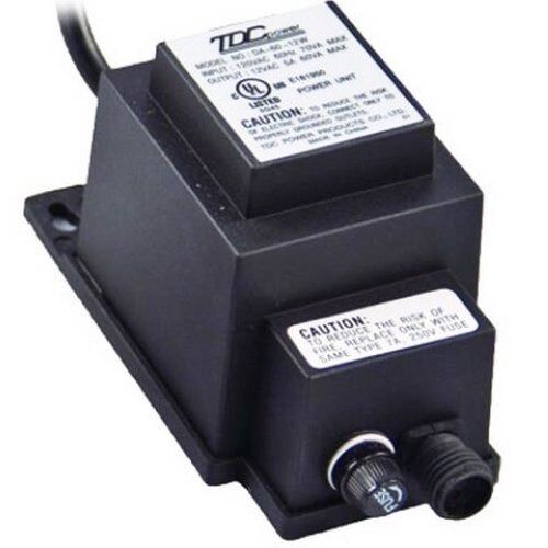
Aquascape 60 Watt 12 Volt Transformer | eBay

Power Inverter 100W, 12V DC to 220V AC - Schematic Design

Intermatic Px100 Wiring Diagram - Wiring Diagram

Wiring Diagram For Low Voltage Transformer

Making a 200 watt Compact PWM Inverter Circuit - Using ...

12V to 120V Inverter Circuit Diagram - Electronic Circuit ...
It uses simplified conventional symbols to visually represent electrical circuits and shows how components are connected with lines. Sometimes wiring diagram can also refer to the architectural. Different transformers and wiring configurations produce Delta or Wye configuration depending on what service is specified for end user.

0 Response to "V Watt Transformer Wiring Diagram"
Post a Comment