V To 3 V Single Phase Wiring Diagram
V To 3 V Single Phase Wiring Diagram. They can also be found in large residential complexes and appliances requiring a large amount of power. In this video we learn electrical engineering basics by learning single phase meter wiring diagram.

A wiring diagram is limited in its ability to completely convey the controller's sequence of operation.
Wiring diagrams and control methods for three phase AC motor.
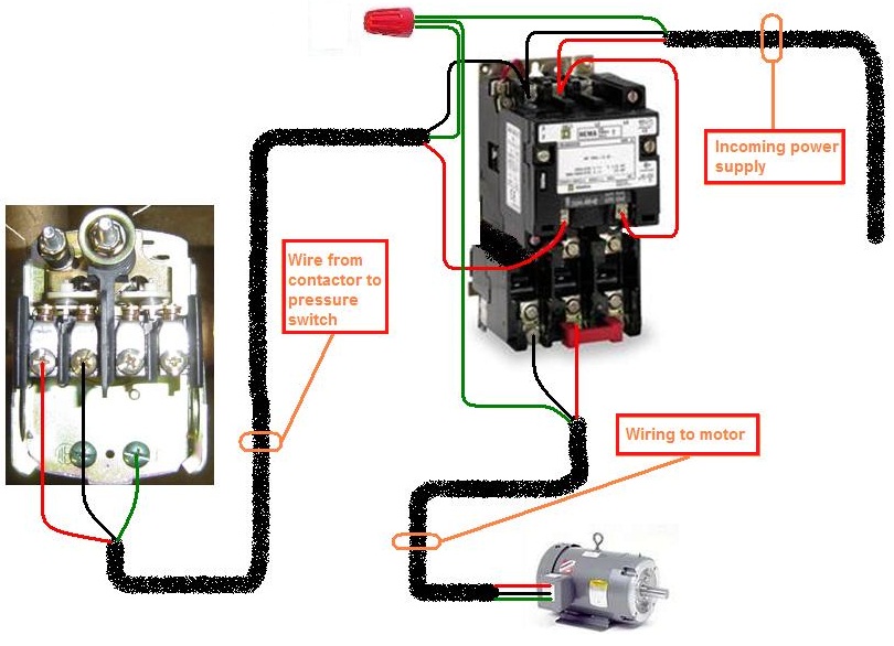
Note: For other posts related to Single Phase & Three Phase Wiring Diagrams… Check the following useful Links Single phase electricity explained. The diagram below shows the wiring for a single phase motor and the path through the contactor and overload NOTE : These notes and diagrams provide a schematic method of achieving the control but it remains the responsibility of the installer to ensure that any safety requirements, local legislation. Wiring Diagrams - Towing Centres UK Ltd.


0 Response to "V To 3 V Single Phase Wiring Diagram"
Post a Comment