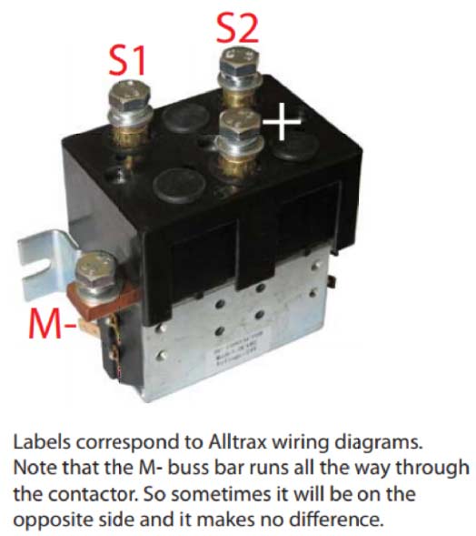
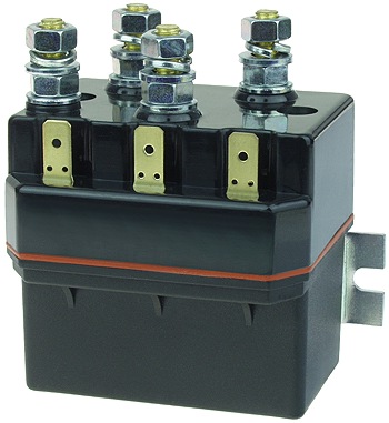
V Reversing Motor Wiring Diagram
V Reversing Motor Wiring Diagram. Therefore wiring a reversing starter for single phase operation is possible but can only be advised for those who fully understand the wiring techniques of their specific single phase motors The diagram below shows the wiring for a single phase motor and the path through the contactor and overload Reverse the wiring. Here you will find the necessary wiring diagrams, schematics, circuits.

This parameter selects the transition mode between Forward and Reverse.
When contacting the negative lead to the diode positive side and the positive lead to the negative side, there should be.
The following diagram is the standard wiring diagram for the VFD-V inverter. Disconnect the wires from the battery and reattach them on the opposite ends of the battery (i.e. white to negative, black to positive). If the circuit has diodes, reverse the two leads and check again.


0 Response to "V Reversing Motor Wiring Diagram"
Post a Comment