V A Wiring Polarity Diagram
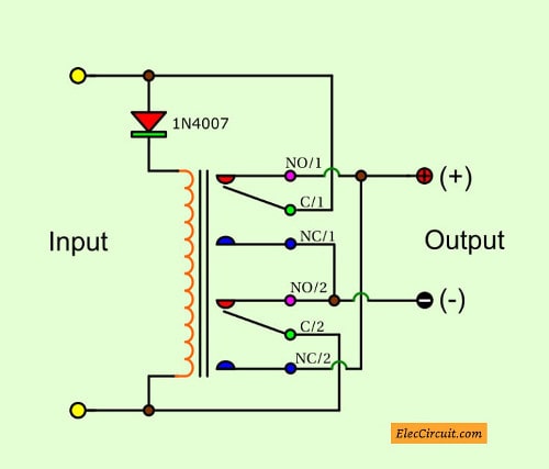
V A Wiring Polarity Diagram. A wiring diagram is a simple visual representation of the physical connections and physical layout of an electrical system or circuit. Now, when you connect the battery as per the circuit diagram, with correct polarity, it causes the transistor to turn ON and allows the current to flow through it.

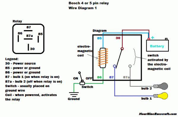
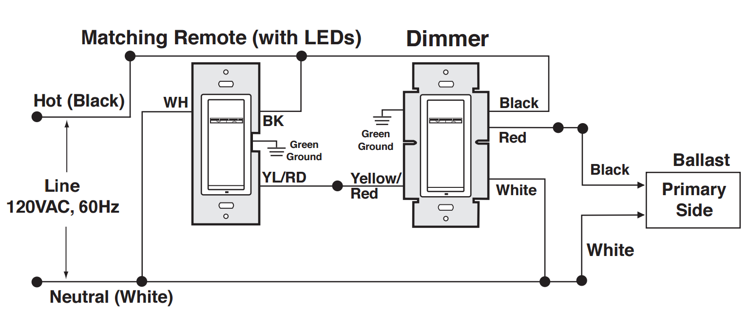
It uses simplified conventional symbols to visually represent electrical circuits and shows how They use the codes or labels to show circuit connector pin numbers, circuit values or component polarities.
A wiring diagram (also named electrical diagram, elementary diagram, and electronic schematic) is a graphical representation of an electrical circuit.
Type of wiring diagram Wiring Diagram VS Schematic Diagram How to read a wiring diagram: Symbols you should know Wiring Diagram Examples A wiring diagram is a visual representation of components and wires related to an electrical connection. WIRING DIAGRAM A wiring diagram shows, as closely as possible, the actual location of all component parts of the device. I am working on a project that uses a linear actuator.


0 Response to "V A Wiring Polarity Diagram"
Post a Comment